Tuesday, September 1, 2015

CAN Bus Sequential Shift light


The idea for this comes from Jon over at Chippernut.com The wiring is basically the same and the fuctionality is simalar to the V1 (http://www.chippernut.com/blog/welcome) but the code has been reimagined from the groud up and uses the CAN Bus libraries from sparkfun to send OBD PID requests over the CAN bus using the MCP2515 chip.

Here is the Github repo for the two versions, one with only the LED strip that works with the above board. and one that has the same sort of settings controlled by the 7seg display and a rotary encoder.
Version 2 is in the works and it adds a Arduino Uno compatible footprint so it can be much more than just a shift light. I just need to order all new surface mount versions of the chips and some new connectors.

Wednesday, July 2, 2014

Uploading sensor data to Thingspeak with the Spark Core

I was able to get the Spark Core to upload data to Thingspeak after looking at some of the examples for using the arduino with the Wifi shield. a few things to note, I needed to put a slight delay after the stream or the spark would close the TCP connection too quickly. 100 ms seemed to do the trick. Also while my example has a delay to keep updates to Thingspeak I suggest using timers because over time the delay (which is blocking) will kill the Spark Cloud connection.

I set up a Sin wav as fake sensor data just to make a cool looking chart. I also setup an inverse of it to demo two streams. Below is the output chart and the example code.


#include "math.h"
// Thinkspeak channel information
String writeAPIKey = "<<Enter your channel's API key here>>";
String channelID = "<<Enter your channel's ID here>>";

// TCP socket initialize
TCPClient client;

float x;
float y;

/*--------------------------------------------------------
Setup
--------------------------------------------------------*/
void setup()
{
    Serial.begin(9600);
    delay(10000);
    Serial.println("===Starting===");
}

/*--------------------------------------------------------
Main loop
--------------------------------------------------------*/
void loop() 
{
    if(Spark.connected())
    {
        for (float z = 4.712; z < 10.995; z = z + .15)      // "z" sets the sin wave to the first zero crossing 4.712 and ends it on the next 10.995.
        {
          x = sin(z) * 127.5 + 127.5;                       // Making the sin wave all positive numbers and setting it to a scale of 0-255 (makes it easy to PWM an LED)
          y = 255 - (sin(z) * 127.5 + 127.5);               // This inverts the sin wave so we have two streams.
          
          // Must convert data to Strings, make sure you use capital "S" in Strings
          ThingSpeakUpdate("field1="+String(x)+"&field2="+String(y));
          
          // I put this delay in place so we don't flood Thingspeak but you should really use a timer, delays screw with the sparkcloud connection some times.
          delay(15000);
        }
    }
}

/*------------------------------------------------
Sends sensor data to Thingspeak
Inputs: String, data to be entered for each field
Returns: 
------------------------------------------------*/
void ThingSpeakUpdate(String tsData)
{
    Serial.println("Date string: " + tsData);
    
    Serial.println("...Connecting to Thingspeak");
    
    // Connecting and sending data to Thingspeak
    if(client.connect("api.thingspeak.com", 80))
    {
        Serial.println("...Connection succesful, updating datastreams");
        
        client.print("POST /update HTTP/1.1\n");
        client.print("Host: api.thingspeak.com\n");
        client.print("Connection: close\n");
        client.print("X-THINGSPEAKAPIKEY: "+writeAPIKey+"\n");
        client.print("Content-Type: application/x-www-form-urlencoded\n");
        client.print("Content-Length: ");
        client.print(tsData.length());
        client.print("\n\n");
        
        client.println(tsData); //the ""ln" is important here.
    
        // This delay is pivitol without it the TCP client will often close before the data is fully sent
        delay(200);
        
        Serial.println("Thingspeak update sent.");
    }
    else{
        // Failed to connect to Thingspeak
        Serial.println("Unable to connect to Thingspeak.");
    }
    
    if(!client.connected()){
        client.stop();
    }
    client.flush();
    client.stop();
}

Tuesday, December 17, 2013

Wireless Qi Charging Car Dock for my Nexus 5


I read the specs on the Nexus 5 as I order it and my thoughts as always go to, "What accessories can I buy/make to make all this cooler?" Then I see the wireless charging. "Sweet I want a Qi car dock so I can just slap it in there and go..." I tell myself, only to find the options are either crappy Chinese made docks that look like crud or $200+ options that aren't all that great either.

At this point my, "They don't make it... Fine I WILL!" mentality takes over and I start digging thru options of Qi charging pads. Reading tons of reviews, digging thru spec sheets, taking measurements, etc. I settle on the Nokia DT-900 charger. It has great review, is the right size, runs on 12 volts, and looks great. The only problem is it retails for north of $40 bucks most places, but oddly enough AT&T has them on sale all the time for $24, and when I ordered them they had 25% off if you ordered 3 or more accessories. So I ended up getting them for $18 a piece. about $55 for all 3 shipped. just a tad more than one other places.

Then I turned my attention to the cradle it's self. I needed something universal, strong, and that would fit with phone and charger. I found the Aduro U-GRIP Plus from Amazon for $20 It had good reviews, everything would fit, and looked the part too.

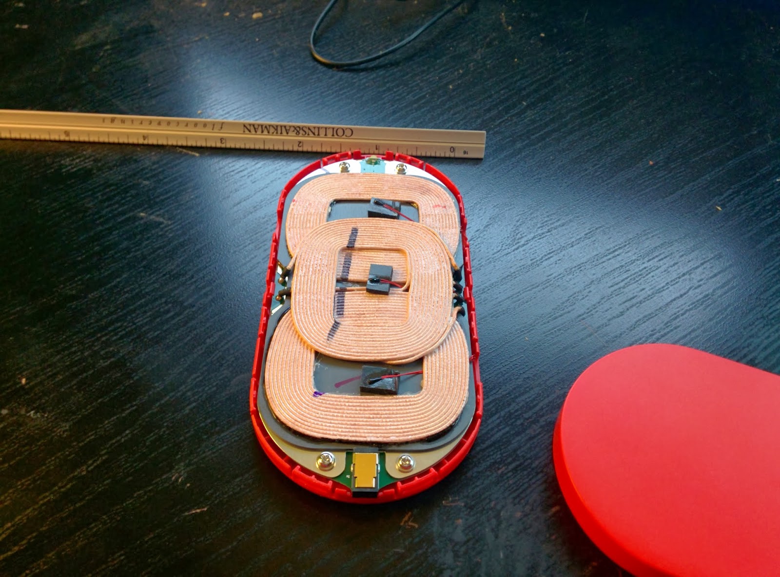
Here are some good shots of the charger torn down. You can see it has 3 pads so it is pretty much one big charger. It's hard to miss the "sweet spot" on it when it is ALL CHARGER. lol


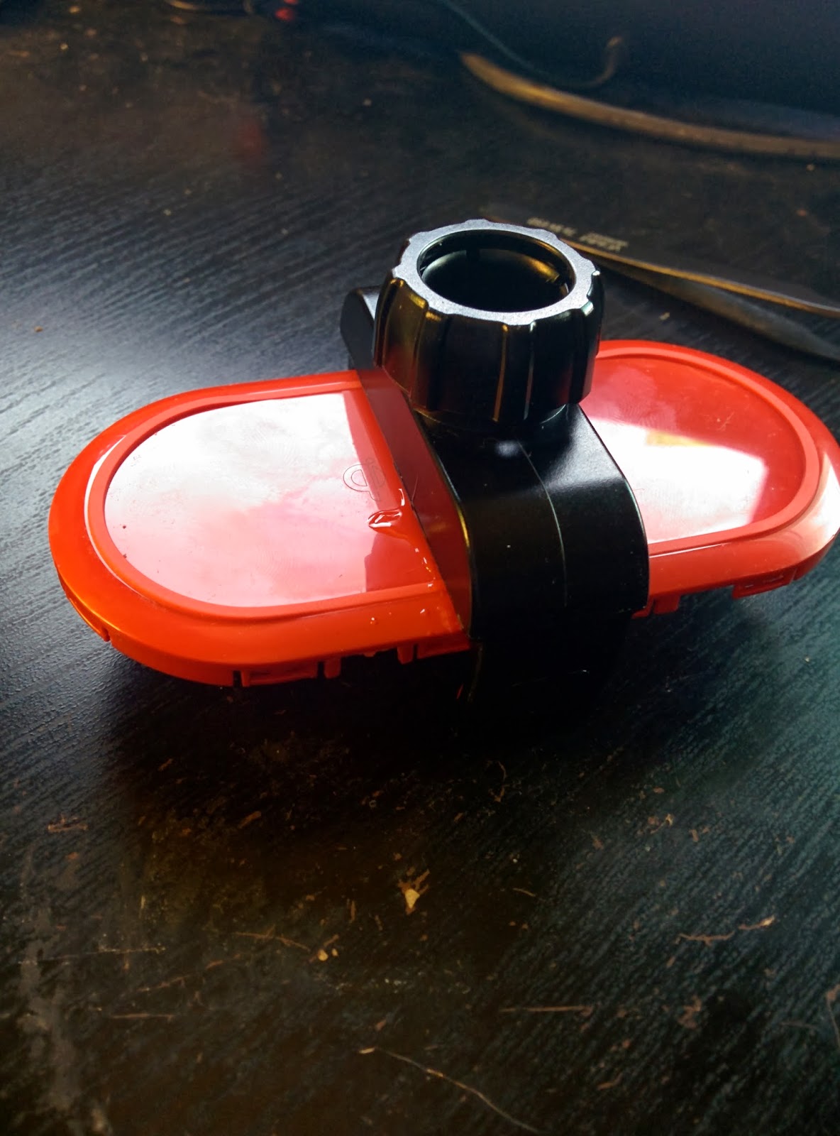
I pulled the gripping pads out of the cradle so I could Epoxy the charger in place on just one of the expanding arms. This gave me an extra 2mm for the phone to fit in the arms a bit better as well.


I wanted to wire it directly to the car and went over board on this part based on some other long term projects in my WRX. I brought a new power cable into the cabin directly from the battery (30amp fused at the battery) then wired it to a brand new fuse block so I can wire multiple things off this new run and not have to "Tap into" other circuits. I did tap into the ACC line so I could use a relay to make the fuse box only live when the car is on. so any of the things I wire off it won't drain the battery. I'm sorry i don't have any pics of this setup but I will work on writing that part up in another post soon.

Also one thing to note here is that the power you get from your car is NOT very "clean". While running the alternator is pumping out 13-15 volts. Second there are massive spikes from different parts turning on and off and relays that are not protected by diodes so 50-80volt spikes are not uncommon. So this should be considered or any bit of electronics wired directly to the car's "+12v" supply will not be long for this world. For the charger (and my radar detector) I built a power supply to keep it below 12v and handle the spikes.

I had some Sharp PQ12RD21's Voltage regulators sitting around so I used those along with a simple TVS circuit to handle spikes above 18 volts. (no I don't have a digital version of the schematic I will get a picture of my notebook soon) For those out there that power supply design isn't in your ball park I'd go get something simple like these maybe these Ebay 3A DC-DC Buck converters with an LM2596S These have a low drop out aswell so that when the car is in ACC and not running ever just the battery at 12ish volts would still put out around 11.5 (I'm guessing here based on the datasheet for the LM2596S) and with my setup 11.5 is still enough to power the Qi pad.

I did some testing with the pad to see what it's current draw was. I ran some tests, a full charge from 0% to 100% This took about 3 hours (about 20% long then a normal full A/C wall charger) Then another test with the phone at around 50% running GPS and Streaming Netflix over LTE. This netted a decrease in battery of about 8% over 4 hours, so that is pretty good in my book. On a recent road trip I kept switching from Torque to Waze and I ended up still charging from 60% to 100% with the screen on for the whole 6 hours, Not sure how long it took but I ended the trip with a phone at 100% :D

With no phone the DT-900 draws about 4mA on it's on and about 30mA once I added the power supply circuit

While charging it draws about 700mA when the battery is low and tapers down as the phone approaches 100% Here it is around 80% and drawing about half an Amp.

The phone is a bit offset since the charger is attached to the lower arm but it still meets up with the charging pads very well.
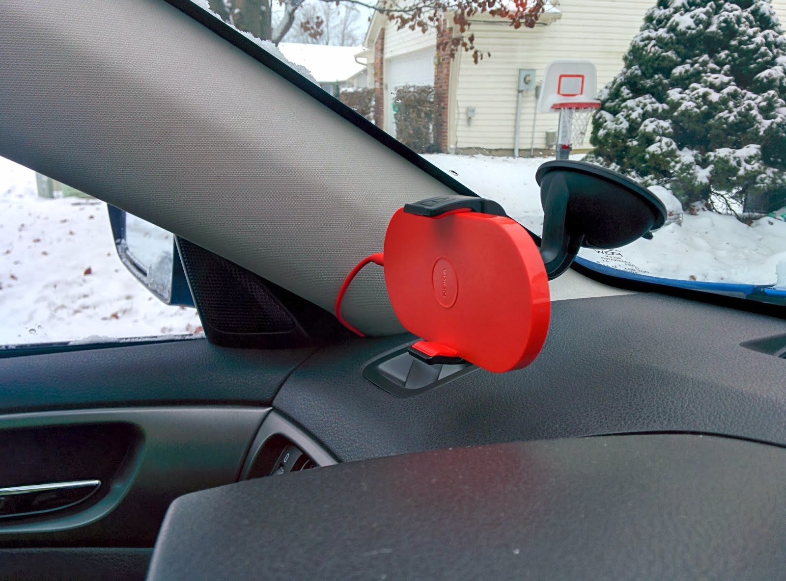
Here we go mounted in the car. It is rather strong, there is almost no wobble when hitting bumps or on rough roads. Over all I'm super happy with the result!


Monday, August 19, 2013

Python Matrix Keypad Package

I packaged up the Matrix Keypad code into a downloadable and installable PyPI package. Let me know if you have any issues but it seems download and install well with PIP and once you make the symlinks to the adafruit code you should be good to go.

Also if there is anyone that has a Beagle Bone that can help me port this over to it aswell I would appreciate it. I've had a few requests but I don't own one yet to do the work on. (unless someone ones to send me one :) )

https://pypi.python.org/pypi/matrix_keypad

Introduction

Python Library for Matrix Keypads. Written and tested on a Model B Raspberry Pi. Supports both a 3x4 and 4x4 keypad included
Current Version:
 v1.1.1
Project Page:Project_Page
PyPI page:PyPI_Page

Author

Prerequisites

If the I2C Port expander MCP23017 or MCP23008 is being used, the Adafruit Python library for I2C and the MCP will need to be installed.
You can clone the whole library like so:
git clone https://github.com/adafruit/Adafruit-Raspberry-Pi-Python-Code.git
or the two files needed can be pulled out, Adafruit_I2C.py & Adafruit_MCP230xx.py.

Install

You can use the source from just downloading the files or Install it as a library via PIP:
pip install matrix_keypad
After the install you will need to create links to the Adafruit I2C and MCP230xx code since they are not installed as packages.:
sudo ln -s [path to Adafruit python cod]/AdafruitMCP230xx/*.py /usr/local/lib/python2.7/dist-packages/matrix_keypad
Note: you will have to change the part in the brackets and maybe the path to the where the matrix keypad package is

Files Included

README.txt
LICENSE.txt
setup.py
matrix_keypad/
    __init__.py
    matrix_keypad_RPi_GPIO.py
    matrix_keypad_MCP230xx.py
    matrix_keypad_demo.py
    matrix_keypad_demo2.py

Usage

See the demo scripts included to see this all in action.
To call the library select which one you intend to use and use the correct line:
from matrix_keypad import MCP230xx
or:
from matrix_keypad import RPi_GPIO
Then initialize and give the library a short name so it is easier to reference later. For the MCP version:
kp = MCP230xx.keypad(address = 0x21, num_gpios = 8, columnCount = 4
The variables here are the I2C address, then if you are using the MCP23017 or MCP23008 you have to put the number of GPIO pin avaialable (default is 8), Then the "columnCount" is 3 for the 4x3 keypads and 4 for the 4x4 keypads.
For the standard GPIO version you only have to reference the 'column count if you want to change it to the 4x4, it defaults at the 3x4:
kp = RPi_GPIO.keypad(ColumnCount = 4)
It is possible to just check to see if a digit is currently pressed.:
checkKeypad = kp.getKey()
Or a simple function to call the keypad library and loop through it waiting for a digit press
def digit():
    # Loop while waiting for a keypress
    digitPressed = None
    while digitPressed == None:
        digitPressed = kp.getKey()
    return digitPressed

Version History

v0.1.0:
Initial Scripts
v1.0.0:
Initial package build
v1.0.1:
Initial package build and push to PyPI
v1.0.2:
Updating the matrix_keypad_demo2.py to demo selecting the 4x4 keypad
v1.0.3:
Moved Version Log in README
Updated README Links
v1.0.4:
Updated References to include the PiLarm code as the inspiration for the "...demo2.py" code
v1.0.5:
Updates to the code in both main libs to fix some indenting and other issues from coping the code from blogger to a text file.
Updates to the keypad picking section for the constants to make it actually work
v1.0.6:
Fixes to more indenting issues. :(
v1.1.0:
Updated main libs and the demo code.
Added install directions to handle the links to the adafruit code
v1.1.1:
Updated ...demo.py and demo2.py to reflect new package name.
Updated README as well

Code References

Column and Row scanning adapted from Bandono's matrixQPI which is wiringPi based.
matrix_keypad_demo2.py is based on some work that Jeff Highsmith had done in making his PiLarm that was featured on Make.

Monday, August 5, 2013

Scrapwood Bike Stand

I had built this a while back but just found all the pictures I took during the process. I spent a ton of time measuring this all out so it would fit together tight and be very strong. It's a bit overkill but it does the job so well. This was about a half sheet of plywood left over from building the router table cabinet. I was tired of leaning my bike against things in the shop so I whipped this up.


Yes that is Flex-seal :) lol


Thursday, August 1, 2013

Adafruit's Simple RF receiver, Testing on an Arduino

I just picked up Adafruit's Simple RF receiver right now I was testing the Momentary type (M4) Which means that while you press the keypad button the corresponding pin on the receiver goes high. I am hoping the next time I order something from them I remember to get the latching one instead because that is what I really need. Anyway since I don't have a project for this one in mind I just wanted to do some testing... so I just plugged it directly into my Arduino( avoiding the Serial pins since I needed those to display the pin states) This is the only way I could fit it on the board without putting it on a bread board. (quick and dirty!)

The VT pin isn't of to much concern for me right now so it just tucks in between the two pin banks :)

Check out the code below. This is great but if I don't want to constantly poll for buttons I may miss one. So my intention is to order a latching version, when you press the button on the keypad the pin goes high and stays high until you press it again. My thought is that if I am powering the receiver from the arduino then I can read it maybe once a second or even less often then when a high state is detected then I can simple "reboot" the receiver by dropping the +5v pin to ground. So until I get one in I will hope it resets back to ground on all the signal pins like I need

/*--------------------------------------------------------
Adafruit's Simple RF Receiver example
http://www.adafruit.com/products/1096                                  
Author: Chris Crumpacker                               
Date: August 2013 

This library is free software; you can redistribute it and/or
modify it under the terms of the GNU Lesser General Public
License as published by the Free Software Foundation; either
version 2.1 of the License, or (at your option) any later version.

This library is distributed in the hope that it will be useful,
but WITHOUT ANY WARRANTY; without even the implied warranty of
MERCHANTABILITY or FITNESS FOR A PARTICULAR PURPOSE.  See the GNU
Lesser General Public License for more details.
                                                           
Sketch Notes: This is set as if you put the reciever directly
onto an arduino with gnd in pin 2 and the VT pin in the 
gap between the pin banks.
--------------------------------------------------------*/

#define GROUNDPIN  2
#define POWERPIN   3

// Arduino Pin Numbers
int signalPin[4] = { 4, 5, 6, 7 };
// Reciever Pin Names
const char* pinName[] = { "D3", "D2", "D1", "D0" };
// Keyfob Pin Names
const char* buttonName[] = { "D", "C", "B", "A" };

int lastSignalState[] = { 0, 0, 0, 0 };
int signalState = 0;
float onTime = 0.00;

void setup() {
  // Set the ground pin to a Low output
  pinMode(GROUNDPIN, OUTPUT);
  digitalWrite(GROUNDPIN, LOW);
  
  // Set the +5v pin to a High output
  pinMode(POWERPIN,OUTPUT);
  digitalWrite(POWERPIN, HIGH);
  
  // Setting the signal pins as inputs
  for (int i = 0; i < 4; i++) {
    pinMode(signalPin[i], INPUT);
  }
  
  // Starting the serial interface
  Serial.begin(19200);
}

void loop(){
  // For each of the 4 pins we loop thru and check the state.
  for (int i = 0; i < 4; i++) {
    // Read the current pin
    signalState = digitalRead(signalPin[i]);
    
    if (signalState != lastSignalState[i]) {
      // if the state has changed...
      if (signalState == HIGH) {
        // ...and the current state is HIGH...
        Serial.print("Receiver Pin: ");
        Serial.println(pinName[i]);
        Serial.print("Keyfob Button: ");
        Serial.println(buttonName[i]);
        Serial.println("Switched ON");
        Serial.println("------------------------------");
        onTime = millis();
      } 
      else {
        // ...and the current State is LOW...
        Serial.print("Receiver Pin: ");
        Serial.println(pinName[i]);
        Serial.print("Keyfob Button: ");
        Serial.println(buttonName[i]);
        Serial.print("Switched OFF after ");
        Serial.print(((millis() - onTime) / 1000.00));
        Serial.println(" seconds");
        Serial.println("------------------------------");
      }
    }
    // save the current state to the last state array
    lastSignalState[i] = signalState;
  }
}

Monday, May 27, 2013

Using an Arduino board as an ISP via the ICSP header

**Moving this over from my instructables so it is also on my blog**

Here are the Gerber Files for an ATTiny84 and 85 along with the board stencils.

I won't go into how to use an Arduino as an ISP, there are plenty of instructables and other how-to's on the net for that.

http://www.instructables.com/id/Turn-Your-Arduino-Into-an-ISP/
http://www.instructables.com/id/Adding-ICSP-header-to-your-ArduinoAVR-board/
http://www.instructables.com/id/How-to-program-a-AVR-arduino-with-another-arduin/

What I needed was a simple way to program (and burn the bootloader) onto my ATtiny chips. I have made a breadboard breakout board (soon to be a different instructable) for my ATTiny84/44s as well as one for my ATTiny85/45s.


These sub-boards are for breadboard prototyping so I don't have to setup the crystal, the power, and the reset every time I want to move to a breadboard.

Step 1:


This is the ATTiny*4 Breadboard breakout. It's the board's traces are a mess I know. I made it with a sharpie marker as I didn't have access to a proper laser printer late at night when I made it. But it works like a charm.

The ICSP header breaks out the chip's MOSI, MISO, SCK, VCC, GND, and RESET pins. That is wired to a normal 6 wire cable. The other end is where the trick comes in.

Step 2:

Typically the ICSP on the arduino boards is used to program the chip on that board. So more like an "IN" as opposed to an "OUT". The reason for that is pin 5 is wired to the reset pin on that chip, and not the reset needed inside the "Arduino as ISP" sketch. I've see "how-to's" that tell you to cut those traces and rewire it. I had no interest in modifying my board permanently so I found it way easier to modify the cable.


Using an 8 pin cable I scavenged I remove the previous cable, then cut 6 wires from an old IDE ribbon cable. After that I pulled the 5th wire from the ribbon cable and made it about 3 inches longer, and did NOT put it into the punchdown for the header.

I punched the other wires in and cut them flush. I put a dab of super glue on both sides of the ribbon cable to try and prevent it from splitting down the cable any more. at the end of the reset pin (5th wire) I put a male connector on it so it would fit into the female pin 10 for programming.


Now all I need to do to program (or burn the bootloader) onto really any AVR that I have a bootloader for is attach this to the ICSP on the slave board and then the other end to my main arduino board and wire up pin 10 for reset. I am able to use the stock "Arduino as ISP" sketch with no mods to the boards or the sketch.